One step at a time

It’s hard to believe the last post was so long ago. Eldest daughter finally bought a house and moved out. Mrs N had the idea of making the now free bedroom into an office/study/hobby room. An idea I couldn’t argue against, as it means not trying to heat the area of the garage by my modelling table during the winter months. Trying to get offspring to remove their “collections” from the parental home is a challenge on an entirely new level. However, the paint has been bought and the room is now ready for decorating.

Progress on the layout has therefore slowed drastically. The Morrison St – Grove St boards have been moved out of the garage, and the rest of the layout, once I can get to it, will be moving out too. In theory, according to the tape measure, there’s space to it to be fully assembled, with the still unbuilt fiddle yard in its new home. The intention is that I’ll bring something home to work on before returning it to the layout.

Davy Scott has completed the railing between the goods and passenger lines at the Morrison St bridge, capturing the essence of a fairly mundane item perfectly, even down to the two types of posts, although he wasn’t able to get the one-legged post to his satisfaction . The two boards definitely capture the atmosphere of the location seen here https://www.transporttreasury.com/p697255697/hf551d8a9#hf551d8a9


The green filler on the tenement? Guess who made it too high and didn’t notice before cutting all the windows and scribing the stonework around the windows and doors…..

Take care

Welcome back my friends….

No. Not celebrating the somewhat overlong delay since my last update.

Having recently spent three, thoroughly enjoyable days at Model Rail Scotland, the first of the ’big’ exhibitions to reappear, its important to recognise the hard work that Ian Porteous and colleagues in the Model Rail Scotland team and the management and staff at the SECCC put into the exhibition against the uncertainties and challenges present by Covid and it’s associated restrictions. Everyone I spoke to, either around the exhibition, or from behind my demo table seemed happy and appreciative. The standard of exhibit was very high, and some of the trade stands continue to raise the bar in terms of professional appearance. A superb return to exhibitions. Possibly, the new ’normal’, is better than the old normal

As tends to be the way, my share of our allocated area wasn’t enough. Fortunately, my friends at the ScRSG are sympathetic to the needs of models of large buildings. Or me! The Morrison St baseboard and various buildings along with a work area just wouldn’t fit a single table.

Davy Scott brought a sample of the railings he’s building for me. It’s evolved quite a bit since the first prototypes appeared, although just placed against the retaining wall, it looks superb and totally transforms the scene. Not obvious from this photo, he has captured posts that have corroded away.


Time was also spent developing a method of adapting Ratio spear fencing into something more suitable for a tenement garden railing. This involves removing the thick post and joining lots of bits together.
Previously, attempts failed as the joints lacked sufficient surface area and strength to support its own weight. The solution appears to be bracing the railing panels with the coping stones from the wall into which the railing is set and a bit of support behind the top rail, courtesy of Evergreen, which disappears when painted black. A little more time is needed to get the spacing correct at the joints when the final version is made, so the eye doesn’t immediately pick up the pattern. The original Ratio moulding is on the left.


So, why do we exhibit?

On the first day of the exhibition, an elderly visitor was talking about Princes St and, noticing the signal box, asked if I was going to complete the interior. He then mentioned that he’d obtained the clock from the box. Our conversation suggested he’d had it for some years, and that his children, not having his interest in railways, didn’t appreciate its history, and were possibly sceptical of its alleged origin.
Four years ago, I’d taken several screenshots of photos of the inside of Princes Street Signal box in LMS days. I can’t remember where I found them, but they weren’t watermarked. The last photo had the clock. Dead centre of the image.

“That’s my clock!”
A copy of the photo was forwarded to the gentleman there and then, and checked that he’d received it before he left me.

A complete stranger had come to the exhibition, and left with something he didn’t know existed, let alone was hoping to get, which adds value to something already in his possession, and it didn’t cost him a penny! To say he was happy would be an gross understatement.

At the end of the day, regardless of how we prefer to phrase it, surely in the most basic terms, we exhibit in the hope of enhancing somebody’s life in some little way?

Take care

The junction

A collection of images from the last six months where work has mainly focused on the Morrison Street/ Gardners Crescent area.

Having been identified as too high, the replacement is more in proportion with the surrounding buildings. Having learned from previous mistakes, the stairwell roof is now cut at an angle to match the main roof before fixing to the wall..
The front of the building, photographed from the rear of the layout, looking up Morrison Street towards Lothian Road.
Looking across the Gardners Crescent bridges. Having built the nearest bridge with solid concrete supports, photographic evidence will no doubt turn up showing the should by cylindrical.
A closer look at the two Gardners Crescent fronts. The lack of the street sign is conspicuous once you’re aware of it.
Tracklaying has commenced, but not yet completed on the goods lines. This required the removal of the bridge section, which will possibly remain off until the ballasting and weathering of the track has completed and the painting of the inside of the bridges undertaken.
The building opposite the new, lower building. These sides face more of the rear of the layout.
The joys of twin pitched roofs! And non perpendicular chimney stacks! Ian Kirk used to advise gluing the sides to the roof on his kits before fixing the floor to reduce to likelihood of the plastic sides bowing. I wonder if the same applies to buildings? It would potentially make it easier to measure and assemble the roof on the flat of a workbench than doing it attached to a large .building
This hopefully will show why background buildings are getting this much attention. A view that only operators will have.
Finally, a couple of aerial views not normally possibly showing the relationship of the buildings to each other.

Take care & remain safe

Keep on running (in)

From a modellers perspective, the one thing Princes St lacks is small, quick, interesting bits of work that make a visual difference. They can probably be counted on one hand, and I’d still have several fingers left over.

One such item is the running in board situated toward the end of one of the platforms. I’d been delaying this as there was little in photos to scale its size from, and I hadn’t seen one turn up on eBay (hoping the seller would declare its size), and was unable to find any information on the internet. In time honoured fashion, I asked some friends.

Who didn’t know! The only guess was possibly 2’6” high. A photo then turned on showing top and bottom edges and the platform signal ladder. Projecting the edges back indicated roughly 3 1/3 ladder rungs. With Gibson signal ladders, this equals 2’6”. One dimension down. The internet does contain information regarding BR Gill Sans font, including an indication os sizes for medium size lettering. Applying this to “Princes Street” suggests a likely length of 7’. Mock ups of the text were created in Inkscape, using white letters on a blue background, so that when printed on photo paper, only the blue would print, leaving the white paper as the text.

test sample in 6’, 7’ and 8’ lengths. The 7’ and 8’ lengths have the spacing between B and U increased to better reflect the original. Printed using a HP Officejet 5740 home printer.

The frame and mountings are made from 1mm brass and 0.31mm nickel silver rods, the lighting unit brackets from scrap etch and the light units from plastic strips.

The final board will be slightly longer to lose the gap between it and the frame, and will be fitted after painting the frame. The droopy light fitting reflects the prototype. The legs may need trimming before mounting in the platform, some of the mounting bolts through the legs need a bit mor reduction, and there looks like some solder still to be removed that was missed.

Back to the larger more time consuming stuff again now……

Bridge over……….

A few(?) years ago, when I first brought notice of Princes St to the then membership of ModellersUnited and others, the original plan for the Morrison St bridge was to use the Wills components for the side. This worked fine for the side nearest the station.

Thoughts about bridge sides never entered consideration when deciding to extend the layout to the Grove St bridge. It was only after buying another pack of the Wills components and examine photos that reality hit. The bridge sides at Grove Street, Gardner’s Crescent Main lines, and goods lines are all different. And none matched the side facing the station.

Initial thoughts were to bluff it. Use the same style of sides on both sides for the main lines on Morrison St. This looked not too bad. It resembled reality if you had a vivid imagination and kept your eyes closed! If you knew what the bridge side was really like….well. Not too many photos exist. However…….

The Grove Street bridge side, to the non-engineering oriented, ie me, is best described as a slab with rivets. To modify the Wills components would require significant cutting, with an excessive number of butt joints the I wasn’t confident I could lose. Knowing the height and length of the side, the decision was made to scratch build and use Archers Rivets to represent the riveting required. To date the rivets have still to be added, but the bridge side so far creates the correct illusion.

The Gardners Crescent bridges are more “interesting“. The sides over the main and goods lines are completely different. The goods lines portion appears to be a welded slab. The passenger lines side is a combination of weld and riveted. Again, Sod’s law makes the Wills components inappropriate for an accurate representation. To further complicate things, the pavement side of one side of the bridge over the passenger lines differs from the outside face. A good view of reality can be obtained from Google Earth, or the Streetview apps, but I’d recommend you move a distance away from the bridge to minimise the distortion caused by looking up from close range. Having initially accepted a loose ‘interpretation’ using Wills components, which was noticeable short for length required, a more accurate interpretation is underway, based solely on photos. Initial progress looks promising. The ‘Niggle’had increased to ‘replace’

Initial attempts using Wills components to replicate station side of bridge. It was uncomfortably tight for length, and unfortunately, looks nothing like the images available on Streetview or discernible from 1960s photos There’s nothing wrong with the Wills product, just inadequate suitability assessment and lack of planning on my part!
The side lighting exaggerates the relief. The bottom section contains the rivets, and is still to be attempted. But it does create a better impression. Once the cunning plan had been devised, it was surprisingly easy to execute successfully.

Other work since the last posting includes more work on the buildings on the Morrison St/Grove St boards. Initial testing to check proportions with adjacent buildings looks good. For some reason, I find that what I consider plain, everyday buildings as (un)interesting to photograph as wiring. No doubt others will disagree!

Looking across Gardners Crescent, over Morrison St. Original layout building with black/white side to be replaced with more accurate version including frontage to Morrison St
Looking down Morrison St towards Haymarket. The building on the right hand side of te road is too high in proportion to it’s colleagues.
Looking west down trackbed with Grove St bridge in distance. Must clean trackbed! The original buildings on right hand side are out of proportion ( too high) with the rest and are scheduled to be replaced.
The factory next to Grove St bridge needs to be raised @ 5mm, and the lean-to nearest the tenement widened a bit. Aren’t you glad we don’t take all the clutter from the models home to exhibitions?
Pavements in place for Gardners Crescent (left) and Morrison St. At 39’ between kerbstones, Gardners Crescent looks wide, but Google Earth measures out at 41’. Interestingly, or maybe spookily, for something laid out by eye to fit the baseboards, the angle and distance between building fronts at the end of the existing pavements is spot on for the real location.

The three bridges have become a welcome diversion. Although unfinished, the basic shapes have been easily defined. The detailing has required a degree of lateral thinking and a couple of trials to determine what works best for me. They have so far delivered a quick sense of achievement and motivation at a time when other ongoing work has longer completion timescales.

That’ll do nicely….

Almost ironically, after the initial lockdowns had finished for some time, my workload focus came to an unplanned stop due to a shortage. Of wood! Three subsequent visits to my local DIY “Superstore” indicate the situation isn’t getting significantly better, and although some materials have been obtained on most visits, a level of compromise has been necessary to complete baseboards and maintain progress.

The second of the two boards that cover the section between Morrison Street and Grove Street bridges has been built and the scenics commenced . Preparatory work on the buildings and structures for these two boards has been completed. Like the main boards, a degree of compromise has been required, relating here to managing the six road exit from the scenic portion for connection to a possible mini fiddleyard will in the garage. This is in keeping with my intention that the model I’m building is an interpretation that captures the character of the location. That is more important than a scale model that doesn’t.

Looking west from Morrison St towards Grove St. Gardners Crescent is in the foreground. Additional support in the form of rectangular box section was required where the cross girders would have been to prevent the bridge insert bending over the running lines when attempting to remove the bridge
The old paint? factory on Grove St positioned to check ground levels and overall proportion for location. Point-work locations for the goods yard point-work between the two bridges. In the real world, the factory has been replaced by a hotel.
The additional strengthening to prevent bending when removing the bridge, before the wood supports for the retaining wall were cut to size.
Far too tidy to be my work area! A good friend volunteered to make the safety railings for the top of the retaining wall between goods and passenger sides of the station and approaches. Complete with the different styles of post used. This is an early view of progress while the best construction methods were being developed

Take care and stay safe

Nearly round the bend

As indicated previously, I’ve recently taken an (enforced) break from the electrical side of things. Taking advantage of “summer”, and some temporary free floor space resulting in a partial tidy of the garage, work has commenced on the first of two scenic extension boards. This carries most of the Morrison St / Gardner’s Crescent bridge. Not wanting an obvious baseboard joint down the length of the road, a piece of 9mm ply was cut to shape, before being abandoned as slightly heavy. It has since been replaced with 3mm styrene, which hopefully will have sufficient bracing and support to prevent it flexing. If not, it’s back to the ply! It’s still early days, but it does have promise as a stand alone photo diorama for stock, and captures the atmosphere of the location

Must remember to hover before taking photos! The building facing Morrison St gives an indication of the view blocker between the two parts of tha layout. The Wills girder bridge is tighter for span length than I though, but possibly ok still. Track omitted from the remaining two goods lines until it can be properly aligned on the next board.

When the ‘new’ Prince Street Station was built, the bridge was extended, and the main lines lowered approx 6ft. The arched bridges over what would become the goods lines, where replaced by girders for roughly the first 25ft of their length. On the model, the main lines are 18mm lower, and the gradient starts just outside the bridge. At this stage, it most be admitted that trying to properly align the goods yard roads without having the second board to Grove St bridge in place, isn’t the easiest thing to do, and does increase the priority to get the timber to get on with that too. Owing to baseboard width constraints, the goods road nearest the edge of the board doesn’t progress far under the bridge, although this is disguised quite well by the angles of the bridge and track.

Photos of the prototype can be viewed at the following links. The end of the baseboard is roughly where the signal is.

https://www.railscot.co.uk/img/29/568/

https://www.railscot.co.uk/img/35/477/

Take care and stay safe.


You can’t always get what you want….

Fifty-two years ago Jagger and Richards probably had no idea their song title would ever appear in a model railway blog. However, their words are very valid.

Forty years ago, I built, from an article in one of the electronics magazines, what was in its day, a state of the art dual power supply that would be used for electronics projects and my model railways. +12V and -12V each delivering output up to 2A, short circuit protected. My interest in electronics waned, but the PSU has faithfully served all my model railways without fault.

Until Monday.

It was the aroma of hot transformer that was the giveaway, confirmed by one of the supply voltage LED on the power box being out. A quick unplugging from the mains and placing the unit at the garage door made everything safe.
Checking next day, scorch marks around the Bridge Recifier, among with a distorted casing suggested it had failed. Testing the 5A rated component with a multimeter conformed it. The failure had occurred before the protection circuitry, rendering it useless. Unfortunately, there was no protection for the transformer output, hence the smell and damage.

Time to find a replacement.

Over the years, as rechargeable or cordless devices have become more efficient and affordable, the number of ac- ac chargers has diminished incredibly. Two or three years ago a search on certain ‘ convenience’ websites identified plenty. Today you can count them on one hand, in some cases, one finger! To replace my split Power Supply Unit, I now need two Separate units, one to become the +ve side, the other the -ve side. To combine them, I’m recommended to follow certain criteria, which reduces the available choice further. The silver lining, is that it will still be cheaper than a replacement build it yourself job. The tradeoff  I have to accept, is that the replacement will be able to deliver 150% more current than its predecessor, more than the wiring in Princes St is rated for, although, fingers crossed, the current protection incorporated into the devices will safeguard that.

I, like many modellers, tend to be a recycler. As such, the controller feeds are from one PSU. Point motors another. Signals/servos a third. LED in buildings or control panel a fourth, and so on. Each with its own voltage and current rating. Possibly each with it’s own style of connector. While we tend to accept that most white goods have an expected working life, and that our parents/ grandparents washing machine/fridge/TV, etc that lasted 40 years don’t  exist any more, it shouldn’t really come as a surprise when something hobby related fails after ten or more years. Yet we don’t plan for it, and it does! Incidentally, the current estimated life of any electronic component without any moving parts is 50 years max.

While a power failure is a a pain for a domestic layout, if it one that is to be exhibited, it is much worse. It can, and does happen immediately before or during exhibitions.
It’s got me wondering, for a layout planned to be exhibited, is the best approach to standardise on a specific rated charger/psu, then multiply as required for the separate systems, then buy one or two extra as contingency for any failures?

Think about it. All supplies delivering the same voltage and max, current, through identical connectors, making it more idiot proof. Any PSU connected into any socket and everything works perfectly.

The worse case by not standardising, in the event of a failure, when you really, really need the fix  “You can’t always get what you want”

Take care and stay safe.


Believe in yourself…

“Believe in yourself. You are braver than you think, more talented than you know, and capable of more than you imagine.”.   Roy T. Bennett – The Light in the Heart.

I don’t think there was a day at any exhibition where I’ve been either demonstrating or exhibiting when I’ve not overheard the phrase “I could never do that”, or some variation of same. When possible, getting the person to sit down, showing them the appropriate tool that I use, giving them a scrap of material and talking them through the process and getting them to try for themselves, and allowing them to keep their attempt demonstrates how simple some of our techniques really are, and hopefully provides the initial encouragement to continue. How quickly it maybe possible to return to that kind of demonstrating when exhibitions restart is anyone’s guess, but I suspect as it’s the one facet of exhibiting that doesn’t easily coexist with social distancing, it’s going to be some time yet.

Until then, try to remember Roy T. Bennett’s words.

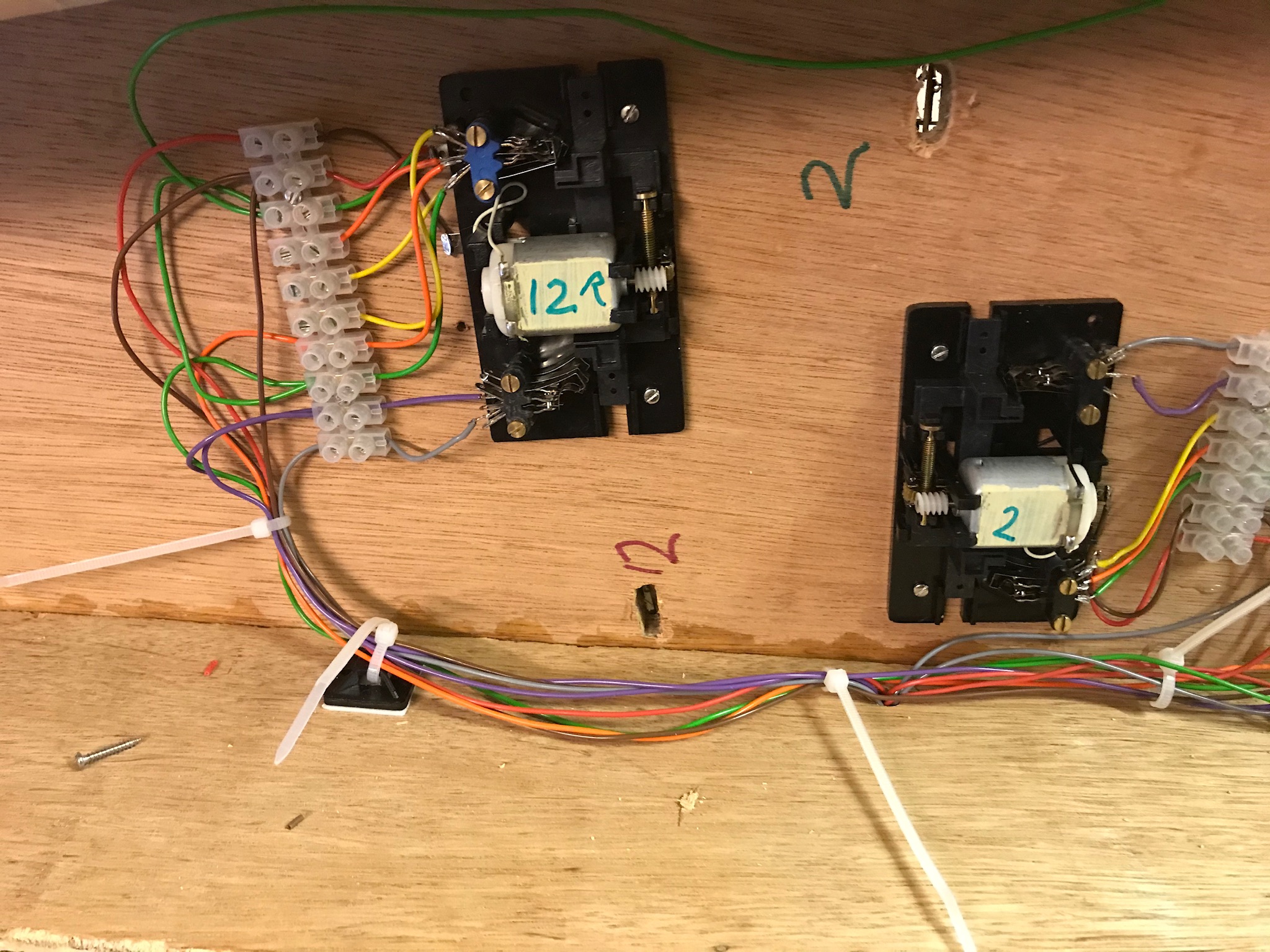
On Princes Street, work continues with the wiring. The relay boards for the signal servos have been installed onto the station throat board, together with their 12v supply and associated wiring. One point motor needed to be moved to a signals servo mounting. The wiring for the scissors crossing frogs has still to be connected back through the point motor switches.
On the more interesting side, in addition to the @180 carriage cleaning supports that were laminated, there were twelve larger supports. Obviously, the twelve were cleaned up first, and the rest are being worked on. I find that a maximum of 20 at a time is about my limit before I need a couple of hours doing something else. Like scribing plasticard, setting an achievable objective for each work session is more important than aiming to finish in as short a time as possible.

09C491D3-DDF6-44B1-A171-27CBA00471B0

A while ago research ended my intention to use the “traditional” long manual lever for the carriage sidings points. Back in my teens, I used some GEM point levers for Farish points on an N gauge layout. It was something vaguely similar to these, but without the robustness functioning levers required. The Caledonian Railway Association indicated these were similar in design, so sufficient were purchased.

8CC51670-230E-42C4-ABCD-456A6D72F02C

Small, fiddly, and benefiting on deciding the best assembly sequence before you start, they build into a very nice model, despite the cruel photography of my first attempt.

F7CA5F65-8603-4F8A-8FAA-CFE1714AFABE


Take care and stay safe.

There’s always one. Or two. Or three…

I don’t know anybody in the hobby who hasn’t had an occasion when things didn’t go quite as expected. Yes, when this happens it can be infuriating, sometimes possibly temporarily soul destroying. However, we tend to become inventive to find a solution that works for us. Sometimes these can be incredibly simply and obvious we later wonder why it took so long to address.

The big board has the most point motors.  Going against conventional wisdom, the baseboard was built without any strengthening cross-members. The idea being they would be added later, after the point motors and wiring were installed to avoid the situation of either having a tiebar above a cross-member, or a crossmember where a point motor needed to go. This has, so far, been remarkably successful. The ply used for the frames and surface hasn’t warped.

There were a couple of tiebars that got a wee bit close though1A682FDA-FB35-48C0-BAB6-65C8A8D7970B

A bit of lateral thinking, and the light bulb goes on! A minor change to the operating bar, relocating the tiebar wire to the end, instead of between the two guides, solves the problem

C53E315C-9020-4B39-A36C-C2EE817FC18C


One material I’ve very rarely seen modelled well is concrete. It has incredibly subtle original colouring and weathering which is far, far too easy to loose at the painting stage. It’s something I need to get right for the platform coping stones and the carriage cleaning platforms and support.

Some time ago, I bought one of the dark grey acrylic washes used by military  modellers. The idea looks quite promising, and needs more experimenting and then to get a better colour matchF473B8A9-4025-41E1-BC02-21357FAC5F91

You do have to make sure you apply the wash in one go, and don’t stop for a coffee. Otherwise you’ll be cleaning it off and starting again,  unless you want puddle outlines!646054D0-B6C4-47FC-8DD8-F2E47432BFF1

Take care and stay safe